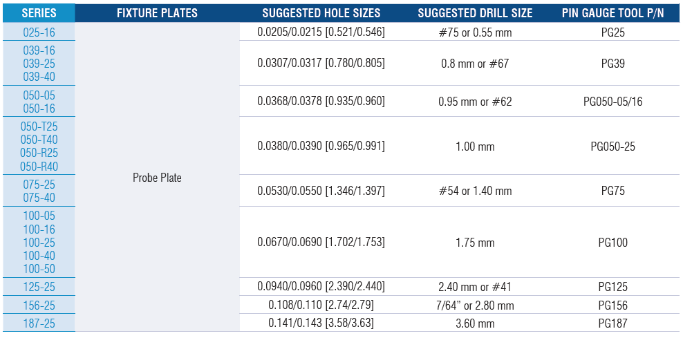
QA Technology recommends hole sizes as shown in the charts below. Suggested drill sizes are for reference only and were derived using AT7000 epoxy glass fixture plate material. Factors such as material, drill tolerances, wear, and machining parameters will affect the final hole size. Each combination should be tested and verified for the application. Use QA pin gauge tools to verify proper hole sizes. Undersized holes could damage sockets, terminations, and installation tools. Oversized holes could result in loose sockets and terminations that would allow the part to move in the mounting plate during testing.

The following charts detail the minimum recommended center-to-center spacing for QA’s conventional sockets and X Probe termination pins. Note: headed probes may require larger spacing depending on their diameter.


Producing fixture plates with accurate hole sizes, positions, and straightness will improve the installation, wiring, and accuracy of sockets and termination pins
QA recommends several drill bit types to achieve optimal holes.

Use a short, rigid center or spot drill to locate the center of the hole, to break through the plate surface, and to leave a small divot starting a point for subsequent drilling operations.

Use a standard carbide circuit board drill to finish the hole. Use an extended flute drill for thicker plates. Peck drilling achieves straighter smaller diameter holes.

Use a conventional high-speed steel drill bit to finish the hole for engineering change orders (ECOs) or when plates cannot be taken apart after steps 1 and 2. This drill type has a long flute length to accommodate a thicker stack up of plates.

Test to determine if the hole is sized correctly by using a pin gauge tool or GO/NO-GO gauges. Verify hole sizes with both sides of the gauge to ensure the hole falls within the correct tolerance. The GO (green) end of the gauge should go into the hole. If it does not, the hole is undersized and must be resized. The NO-GO (red) end of the gauge should not enter the hole. If it enters, the hole is oversized, and the plate may need to be re-drilled.

With thick mounting plates, drill optional stepped holes or use multiple thinner plates to improve hole straightness. Position the properly sized hole on the critical surface and a larger clearance hole on the non-critical surface.
With X Probe fixtures, the bottom of the spacer plate is critical. It helps guide the end of the probe tube/interconnect housing onto the termination pin during installation and replacement.
When using guide plates, it is necessary to back drill the bottom to make it easier to align the probe tips during installation. This provides added clearance for the probe and socket tubes when the guide plate is actuated.
