Test probes are designed to be used at their working stroke, typically two thirds of their full stroke capability when testing. Test fixtures should be designed and built so that sockets or QA X Probe® termination pins are set at the correct height for probes to stroke at the working stroke when actuated by the unit under test (UUT).
When set too low, the spring force may be insufficient for a reliable electrical contact with the UUT. When set too high, the plunger will be over-stroked, causing early spring fatigue, tip damage, or other premature failures. Setting probes at the proper working stroke will achieve the highest first pass yields, maximize probe life, and reduce overall maintenance costs.
You can easily measure how much a probe is actuated during test by using QA’s indicator probes. Indicator probes must not be used as electrical contacts as they remain compressed at the test position when actuated.


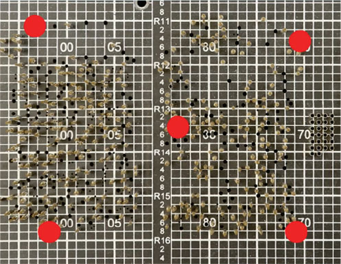
Before installing indicator probes, remove the support plate and select a location to measure the current stroke of the probes. To get a good indication of the overall probe stroke in a fixture, it is common to measure at each corner of the probe field, and once in the center.
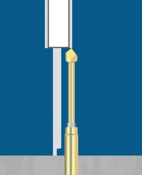
Measure from the top of the probe plate surface to the tip of the standard, unactuated probe at each location where the indicator probes will be used. This will be used as “Dimension A” in the calculation. Hand-held calipers are perfect for this.

Replace the standard probes at each of the five locations with indicator probes. Pressing down as far as they will go, the plungers will stick down.
Using tweezers or needle nose pliers, pull up on each of the indicator probe plungers, bringing them back up to their original position. Be careful not to pull the probe out of the socket or termination pin.
Reassemble the fixture and cycle one time only. The indicator probe plungers will remain in the deflected position, showing their position when the fixture is actuated.

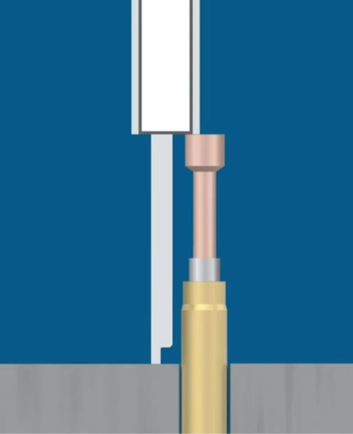
Measure from the probe plate surface to the actuated indicator probe tip. This will be “Dimension B” in the calculation. Repeat at each indicator probe location to ensure that all are stroked a similar amount across the entire field.
The height difference between the original test probe and the indicator probe is the amount of plunger stroke that occurs when the fixture is actuated in production.
Example:
0.580 Dimension A (height of the existing probes in the fixture)
– 0.413 Dimension B (height of indicator probe from the top of probe plate)
= 0.167 Amount of probe stroke when the fixture is actuated in production
Compare the actual plunger stroke findings to the “working stroke” rating for each probe series listed in our catalog/probe guide or website. Sockets or termination pins should be lowered if probes are being over-stroked. If they are being under-stroked, sockets or termination pins must be replaced at a higher set height to achieve the proper stroke.
Remove the indicator probes and make any necessary modifications to the set height of the socket or termination pins.
Re-install the original probes and reassemble the support plate back onto the fixture. Now you are ready to use the fixture.
Select a headless probe in the location that will measure the stroke of probes hitting vias or test pads. Use a headed probe for a location that will test a lead or post.
Replace an indicator probe after a few actuations as it will lose its ability to remain in the deflected position.
Instructional video on how to measure probe stroke in a fixture