For QA’s X Probe® fixtures, the termination pin set height is the distance from the top of the back plate to the shoulder of the termination pin. Probe performance and longevity are maximized when the termination pins are installed to the correct set height. When set too low, the probe is under-stroked, reducing the contact force and the probe’s ability to penetrate surface contaminants. When set too high, the probe is over-stroked, which may cause reduced spring life, risk damage to the unit under test (UUT) or incur tip damage due to bottoming. To calculate the proper set height, follow these steps:
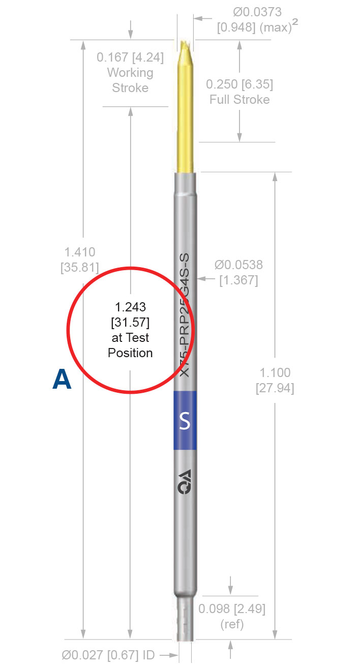
Retrieve dimension (A), the “at Test position” from the product series page of our catalog or website. This is simply the difference between the overall length of the X Probe and the working stroke. It is important to note that these dimensions may vary from series to series, so a separate calculation must be made for each probe series used in the fixture.
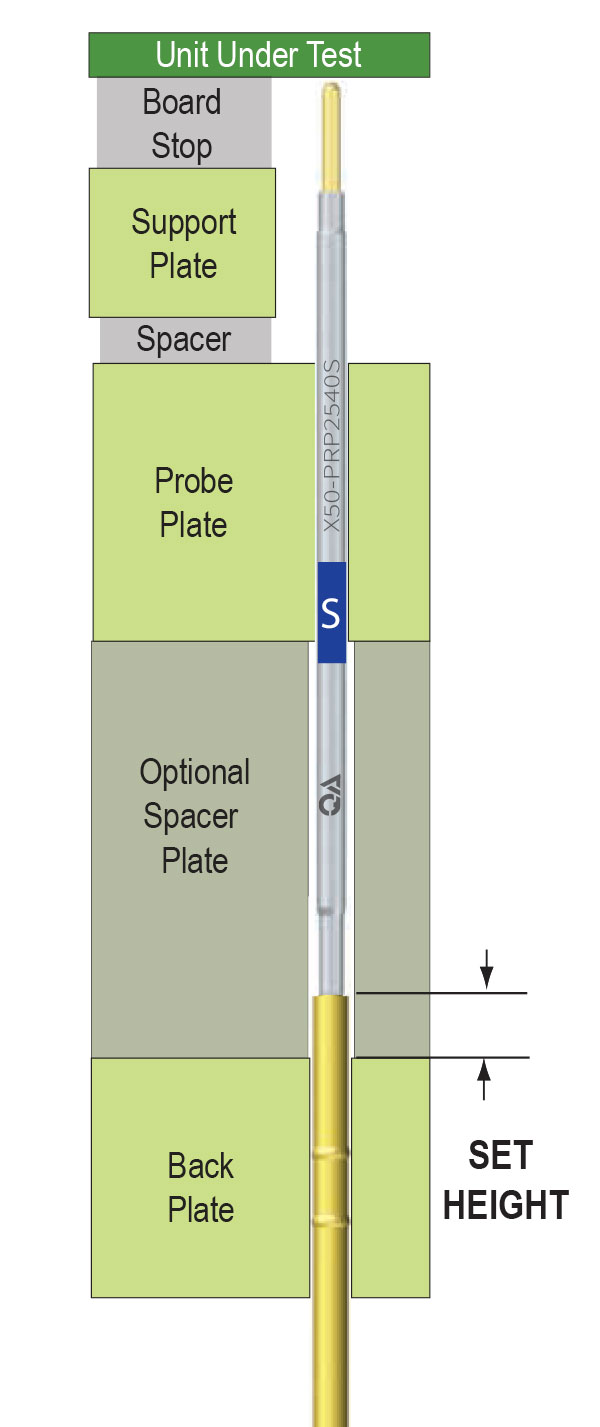
Make a cross-sectional sketch of your fixture to calculate the total thickness of all fixture items that stack up between the top surface of the back plate and the UUT when the fixture is in the actuated position. This includes the probe plate, spacer plate, spacers, support plate, and board stops. This diagram is one example of a typical fixture.
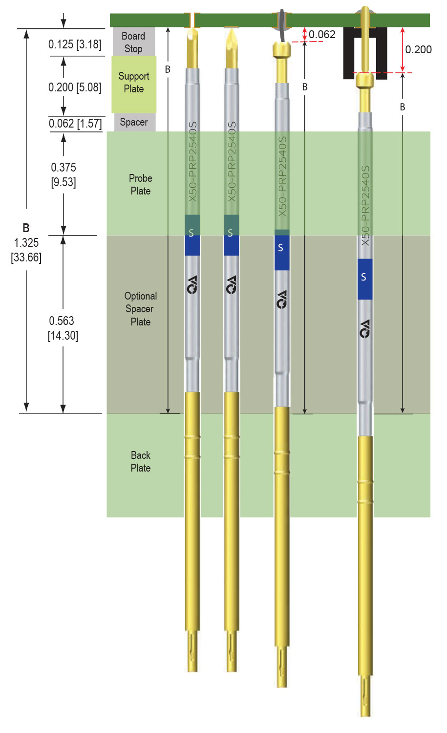
Add the thickness of the items that stack up on the top surface of the back plate to the contact surface of the UUT to get dimension (B).
If contacting leads, posts, or components, subtract the average length of these to adjust dimension (B).
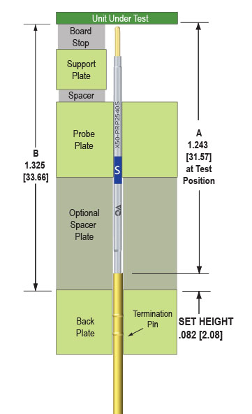
Subtract the at test position dimension (A) from total stack-up dimension (B).
Example X50-25:
1.325 [33.66] (B)You can now use this set height dimension to install your termination pins with our ITR preset installation tools.

To account for irregularities in the hole mounting, a margin of at least 0.020 [0.51] is recommended between the retention beads and the closest plate surface.
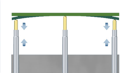
Consider board flexing and bowing. Be sure that all probes are stroked to at least their working stroke.
Instructional video on how to calculate X Probe termination pin set heights.