
This test report presents the data and describes the procedures for testing the current carrying capacity for QA Technology’s test probes and their respective mounting sockets or termination pins. The current carrying ability of a probe is ultimately determined with respect to probe temperature. (Refer to the Applications Note titled Working Temperature Ranges for additional information.) QA’s testing was performed at a nominal ambient temperature of 20°C. The final current carrying capacity of a probe will depend upon many additional factors specific to the actual application.
The maximum temperature that a probe can handle is determined primarily by the spring material and the lubricant used. Ratings for probes with music wire springs are limited to 120°C, while stainless steel springs with high temperature lubricants can handle up to 204°C. Ratings at both temperatures are outlined in their respective product pages. Note that only certain, specific products use both a stainless spring and hightemperature lubricant.
Although our current and temperature ratings are based on our product materials, many fixture materials will not tolerate temperatures up to 204°C (some plastics will not even withstand 120°C). Many solders may become weak or even melt well below this temperature. Precaution is advised if operating probes at very high temperatures.
QA Technology’s current test system consists of a multichannel data acquisition system, programmable DC power supplies, a test fixture chamber shielded from room air currents and an industrial PC to provide test configuration, control and data recording. The test fixture chamber provides connection points for one or two test fixtures at a time, and it also has thermocouples installed for measuring the ambient air temperature during the test.
For our conventional probe series, FR4 test fixtures were built to mount eight probes at a time for testing. Standard 0.250 [6.35] stroke probes were stroked to 2/3 of their nominal full stroke. Long stroke 0.400 [10.16] probes were tested at 0.075 [1.91] stroke which is commonly used in dual-level fixturing. The probes were spaced 1.00 [2.54] apart to provide effective thermal isolation between individual probes. A circuit board was designed to allow all eight probes in one fixture to be connected in series. The surface of the circuit board was coated with solder to simulate typical contact conditions between the probe tip and a circuit board under test. The sockets were interconnected to complete the series current path. The wire gauge used for interconnecting the sockets was selected according to the expected test current.
Fine gauge type T thermocouples (Copper/Copper-Nickel) were soldered to the sockets just below the bottom surface of the socket mounting plate. The fine gauge thermocouple wire minimized heat transfer from the socket and decreased the thermal response time. The thermocouples were then connected to the multi-channel data acquisition system.
In the case of QA’s X Probes®, the test thermocouples were attached directly to the probe tube wall just above the tube’s interconnect receptacle. The X Probe termination pins were connected in the same fashion as the sockets for conventional probes.
For testing wireless sockets and termination pins, the test fixtures were designed so that both the test probe and wireless interface probe are part of the current path. The interface board was spaced so that the plungers were compressed to the recommended stroke and a flat gold pad was used for the contact point. The gold contacts on the interface board were wired to complete the series current path and a thermocouple was soldered to the wireless interface probe tube to monitor the temperature of the interface probe assembly. In general, the current carrying capacity of the wireless sockets and termination pins were less than a standard wired socket and termination pin assembly due to the additional interface probe.
A programmable DC power supply was used to provide a constant test current through the probes and sockets or termination pin being tested. The current was programmatically incremented and the assemblies were allowed to reach a stable temperature before the readings were recorded. This process was repeated until the required temperature rise was achieved across a majority of the probes under test.
The wire gauge used for interconnecting the sockets or termination pins of the probes under test varied depending on the final current requirements for the test. Indeed, the choice of interconnect wire gauge played a significant role in determining the temperature of a particular probe during testing. A heavier gauge wire ran cooler for any given current, with the copper conductor acting as a heat sink for the probe under test.
Three sets of tests were conducted and analyzed statistically to produce a temperature vs. current curve based upon a 3-sigma rise above the average data values. The final current carrying rating for the probe was derived from this curve. Using this 3-sigma standard, 99.7% of all probes will meet the current rating.
The M035-14, M08-89, and M100-75 probes’ setup utilized fixtures designed around the typical applications for these probes and consisted of two plates with the probes captured between a top and bottom plate. A small cross-channel was machined in the plates to allow room for the thermocouple wires. Two circuit boards sandwiched the top and bottom plates to route the series test current through all eight probes.


Probe Mounting Density - Higher probe mounting densities decrease the probe’s current carrying ability. This is due to the combined heat generated by the probes and the decrease of air circulation via natural convection. Because each application is unique, it is recommended that appropriate tests be conducted before probes are put into service in applications with high currents, high probe densities or limited airflow.
Probe Cooling - These temperature measurements were made in the absence of any forced convection. Providing airflow (by means of a fan, for example) around the sockets or termination pins will reduce the temperature for a given current. Also, tests have shown that the airflow present due to leaks in a typical vacuum fixture will reduce temperature.
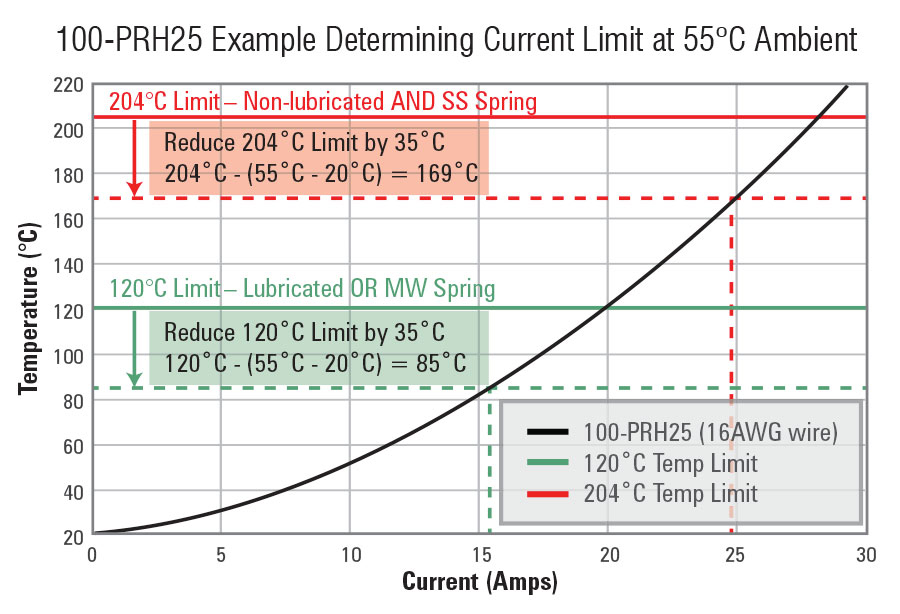
Elevated Ambient Temperatures - For conditions where the ambient temperature differs from the 20°C ambient of these tests, a simple graphical technique can be used to obtain a corrected current limit; shift the temperature limit line down by the same amount that the actual ambient temperature exceeds 20°C. For example, a 100-PRH25 series probe operating in an environment with an ambient temperature of 55°C will exceed 120°C at 15.4 Amps and 204°C at 24.7Amps (instead of 19.8 Amps and 28.3 Amps respectively at 20°C ambient).
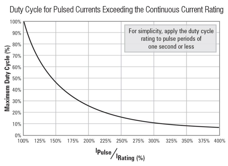
Duty Cycle for Pulsed Currents - This data reflects performance at 100% duty cycle. Higher currents can be carried for pulses of short duration. For simplicity, apply higher currents for no longer than one second (longer pulses may be carried, but require that thermal inertia and rate of temperature gain be known). A probe’s ultimate temperature is determined by the dissipated power [P=I2R], so duty cycle adjustments should be made according to the square of the current ratio. For example, a 100-PRH2509X in a 100-SDH250W is rated for 19.8 Amps. If you want to run it at 35 Amps, the duty cycle would need to be (19.8 ÷ 35)2 = 0.5662 = 0.32 = 32%. So, to avoid overheating this probe at 35 Amps, power must be applied for no more than 320 milliseconds (1 second x 32%). Similarly, the 187-25 Series of probes and sockets are designed for high current applications given the larger component diameters and greater internal contact surfaces areas when compared to the other series. A 187-PRH2509H probe in a 187-SDH250S socket carries a maximum continuous current of 41 Amps. To carry 75 Amps it would need to be run at a 30% duty cycle (59 ÷ 75)2 = 0.619 = 62%.
Reference Point - For comparison purposes, note that a 16 AWG, Ø 0.051 [1.30] solid copper wire close to the same diameter as a 100-25 series probe tube, Ø 0.054 [1.37] reaches 120°C at 31 amps.


